New Release?

General discussion about the sport of hang gliding
User avatar
Tad Eareckson
Posts: 9149
Joined: 2010/11/25 03:48:55 UTC

Re: New Release?

Post by Tad Eareckson »

Do you agree?
No.

- From zero to 85 pounds direct loading - the point at which the slop's taken out of the system as indicated by your testing - you're doing eleven pounds.

- Above that to the point at which you're permanently distorting the pin you're adding eleven pounds of spring compression to whatever it is you'd need to overcome the other resistances of the assembly.

- And once you start rolling you can throw the fuckin' spring away (assuming the towline never goes slack again before you get to altitude). All the spring does is keep the bridle from falling loose while you're prepping for launch.
I'd want to do this even if it wasn't necessary for normal tensions (i.e., if I used a lighter spring).
Yeah. But you shouldn't need to be gearing yourself for and delivering an adrenaline pumped long jerk to get yourself off of a worst case scenario.

Again... Throwing my basetube bungee out of the system, I can blow 650 towline with a twelve pound pull and an inch or so of hand movement (or no hand movement other than a motorcycle throttle type twist) or whatever I choose to set the lanyard play to. (But I don't wanna set it too tight or I'll find myself off tow at an unacceptably low altitude. (BTDT.))
Even if boosted?
- To use mechanical advantage you're trading movement for power.

- The movement you need to effect at the business end of the primary...

http://www.flickr.com/photos/aerotowrelease/8306258400/
Image

...is just what it takes to pull that stubby little barrel off the end of the pin - about fifteen millimeters.

- I have the lanyard routed through two pulleys at the top end of that system.
-- One just redirects the lanyard as it's coming out of the downtube.
-- The other doubles the mechanical advantage.

- With my two to one mechanical advantage I need to pull (call it) 10 millimeters of play out of the lanyard plus thirty millimeters to move the barrel.

- If I threw another pulley into the system for a three to one mechanical advantage I'd hafta pull 10 plus 45 - a little over two inches.

- But it would be a helluva lot smarter just to get somebody to cut me a longer pin. Then there'd be no movement penalty for the mechanical advantage.

- But, hell, I don't need any more mechical advantage 'cause I'm using a 272 pound weak link and I'll never hafta pull as much as nine pounds.
It looks like a pulley has to be screwed into the downtube.
It needs to be HARNESSED TO the downtube. And there's no surgery involved there. Just swap out the clevis pin that normally secures the top end of your downtube for the slightly longer stainless steel screw you need to secure the harness.
Zack C
Site Admin
Posts: 292
Joined: 2010/11/23 01:31:08 UTC

Re: New Release?

Post by Zack C »

Tad Eareckson wrote:From zero to 85 pounds direct loading - the point at which the slop's taken out of the system as indicated by your testing - you're doing eleven pounds.
85 is just the maximum I could do with the weights I had...I never tested above that.
Tad Eareckson wrote:Above that to the point at which you're permanently distorting the pin you're adding eleven pounds of spring compression to whatever it is you'd need to overcome the other resistances of the assembly.
I have a hard time understanding the implications of that.

OK, let's try this...
If 'a' is the actuation force and 'l' is the load, this was my mental model of their relationship:
a(l) = 11, l <= 165
a(l) = l / 15, l > 165
Is this accurate? If not, can you express the relationship either mathematically or with a graph? If a spring of negligible strength was used, how might the new relationship look (mathematically or graphically)?

Thanks for bearing with me...
Tad Eareckson wrote:But it would be a helluva lot smarter just to get somebody to cut me a longer pin.
I might be able to make that happen...

So with a long enough pin, you could remove all the pulleys without an increase in actuation force?

Zack
User avatar
Tad Eareckson
Posts: 9149
Joined: 2010/11/25 03:48:55 UTC

Re: New Release?

Post by Tad Eareckson »

85 is just the maximum I could do with the weights I had...I never tested above that.
Alright. But - in the absence of more data - let's pretend that that's what does it 'cause:

- it's probably close; and
- none of this stuff is the least bit critical.
OK, let's try this...
I don't know where 165 is coming from.

85 direct load (bridle tension) translates to 148 towline.

165 towline translates to 95 direct.

Let's use 85 as the point at which the Spectra length maxes out and assume that the spring when fully compressed is 11.

Up to 85 the most pull you can have is (11) plus (the load divided by fifteen).

You're ALWAYS gonna have the load over fifteen plus whatever it takes to squish the spring (no more than eleven) enough to clear the pin.

Let's say that at 85 the Spectra's stretched out as much as it's gonna get and it will now and from now on take nine pounds to squish the spring enough to clear the pin.

Now we know that the pin squish has gotta be from eleven to nine so we know that the possible required pull range from zero to 85 is 11 to (85/15 + 9 =) 14.7.

After that it's just load over fifteen plus nine.
If not, can you express the relationship either mathematically or with a graph?
Load on the X axis, actuation on the Y.

Kinda flat, maybe dipping somewhere, but generally climbing to 85 - then a smooth steady climb.
If a spring of negligible strength was used, how might the new relationship look (mathematically or graphically)?
Straight line from the X/Y intersection to the upper right.
Thanks for bearing with me...
Thanks for staying in the conversation. Data and equations are the only things we have to protect us against Rooney, Davis, and Tracy and their idiot opinions.
I might be able to make that happen...
We don't really need it to. That little two and a half dollar parachute pin is overkill for anything any of the current tugs can throw at us. And even on your platform stuff you're using six hundred pound weak links.
So with a long enough pin, you could remove all the pulleys without an increase in actuation force?
No.

- I have three pulleys.

- Two of them - the one harnessed onto the downtube and the one on which the release mechanism is built - are necessary to redirect lanyard tension.

- Only the one around which the lanyard is routed produces any mechanical advantage.

If you go with a long pin...

There's no downside if you use cable - but cable is a royal pain in the ass.

If you build your system in - the way the job SHOULD be done - and use leechline, then you MUST tension to the nose so you can handle slack line.

When you tension to the nose the bridle tension is trimming you more nose down than you would be if you were just anchoring from one point a bit in front of your hang point on the keel.

You may be trimmed down more than you wanna be already.

And if you get a bottom end bridle wrap you're gonna be dead a lot faster than you would otherwise.

And a long pin limits your ability to trim aft.

It's a damn good system as it is. Take out one pulley and cut the mechanical advantage in half - it's still a damn good system.
Zack C
Site Admin
Posts: 292
Joined: 2010/11/23 01:31:08 UTC

Re: New Release?

Post by Zack C »

Tad Eareckson wrote:You're ALWAYS gonna have the load over fifteen plus whatever it takes to squish the spring (no more than eleven) enough to clear the pin.
Then why am I measuring an actuation force of only 11 when the load is 85?
Tad Eareckson wrote:I don't know where 165 is coming from.
15*11. With an L/A of 15, it's the load that requires an actuation force equal to the minimum (no load) force. My thinking was that with loads less than that, the required pull would always be 11. Above that, it would start to increase.

Anyway, if I'm following you, the equations would be:
a(l) = (l/15) + c(l), l <= 85, where c(l) varies between 11 and 9 (maybe c(l) = (-2/85)l + 11) (the equation for a line intersecting (0, 11) and (85, 9))
a(l) = (l/15) + 9, l > 85
If that's the case, a(85) should be at least 14.7...again, I measured 11.
Also, the L/A ratio is not going to be 15, and it's not going to be constant (instead increasing with load). For example:
a(100) = 15.67, L/A = 6.38
a(200) = 22.33, L/A = 8.96
a(300) = 29.00, L/A = 10.34
Joe said he could release 330.7 lbs (150 kg) with a 17.6 lb (8 kg) pull. This is the only data point I have with an actuation force over the no-load force. That's an L/A of 18.75.
If we wanted to make the slope of our equations above match this data point, it would need to be 0.0261 (instead of 0.0667):
a(l) = 0.0261*l + 9
Then
a(100) = 11.6, L/A = 8.6
a(200) = 14.2, L/A = 14.06
a(300) = 16.8, L/A = 17.81
which may be more realistic. However, this is all theoretical...we really need some more data points. Do you have any, Antoine? I wish I had a way to get some for higher loads...
Tad Eareckson wrote:Two of them - the one harnessed onto the downtube and the one on which the release mechanism is built - are necessary to redirect lanyard tension.
OK...so I'd need to do the downtube pulley regardless. It looks like I don't have to do anything for the other ones (beyond just attaching the upper assembly).

Zack
deltaman
Posts: 177
Joined: 2011/03/29 11:07:42 UTC

Re: New Release?

Post by deltaman »

Zack C wrote:Joe said he could release 330.7 lbs (150 kg) with a 17.6 lb (8 kg) pull. That's an L/A of 18.75.
good news.
Zack C wrote:we really need some more data points. Do you have any, Antoine?
no, but :
Joe Street wrote:Without considering friction in the cable (which can be considerable if poorly installed!!) it takes about 5kg just to compress the spring. This is added to the force needed to retract the barrel. At high load we can simply divide the force applied to the release pin by the force applied to the lanyard and get some number like 15:1. At very high loads it might look even better, but if we put only 5k load on the pin we find the number is more like 1:1 so we need to realize it is not a simple statement especially when cable friction is also factored in. I may have had old data in my notes which didn't consider the spring force as I know *I did a bunch of testing at first just with the pin, a tube and a fish scale.
Tad,
- I'm surprised that the rubber band inside the controlbar is enough to release a 16.4 L/A remote release even with a two to one mechanical advantage: x2 = 32.8 L/A: with 200kg towline load, I need 3.5kg actuation force. Can a rubber band do that !?
- it will still be a good system without the controlbar parts, all included in the downtube as a VG system: a leechline to pull exiting the low end of the downtube and the two to one mechanical advantage inside the downtube.. it's probably what you thought for manufacturers as WW.
- what about the friction of the leechline inside the plastic tubing (downtube entry and exit) ?
- this plastic tubing won't finally slide in or outside the hole of the downtube ?
-
Tad wrote:If you build your system in - the way the job SHOULD be done - and use leechline, then you MUST tension to the nose so you can handle slack line. (..)
And if you get a bottom end bridle wrap you're gonna be dead a lot faster than you would otherwise.
that's a big deal !!! if the tension is necessary in front of the release, it's not necessary to the nose
User avatar
Tad Eareckson
Posts: 9149
Joined: 2010/11/25 03:48:55 UTC

Re: New Release?

Post by Tad Eareckson »

Then why am I measuring an actuation force of only 11 when the load is 85?
If you look at your no load test video (like I did again after reading this)...

That spring is nowhere NEAR bottomed out when the release fires. And it's gonna be a lot less bottomed out when the load is 85 pounds.
15*11.
No.

- Fifteen is ALWAYS a denominator (unless you're measuring your pull and trying to figure how much load you just dumped).

- The spring NEVER gets multiplied by anything - just added to or subtracted from. And if eleven is the bottomed out force - just subtracted from.
My thinking was...
If eleven is the slack line figure I would predict that as you start loading up the release and elongating the Spectra the required pull will drop for a bit before it starts going back up.
If that's the case, a(85) should be at least 14.7...again, I measured 11.
Working backwards...

- You measured the slack line pull at eleven - that's all spring compression and the spring compression will only go down and stabilize as you load things up.

- You also measured eleven at 85 pounds.

- The load to actuation ratio is fifteen so 5.7 pounds is friction and 5.3 is spring.

- And the spring should be accounting for only 5.3 (or less) from that point on.
...and it's not going to be constant...
Yeah, you're throwing a constant spring compression factor into the equation and the more you load things up the smaller the fraction of the pull the spring's gonna represent.
This is the only data point I have...
That's the only data point you NEED. That's just 25 pounds towline under your tug's weak link - and 227 pounds towline OVER your current weak link - and the pull is about a fifth of what you're gonna be doing when the adrenaline kicks in.

(I wish I could get you to do fewer equations and more drilling. (Drill, baby, drill!))
I wish I had a way to get some for higher loads...
That load tester...

http://www.flickr.com/photos/aerotowrelease/8317889807/
Image

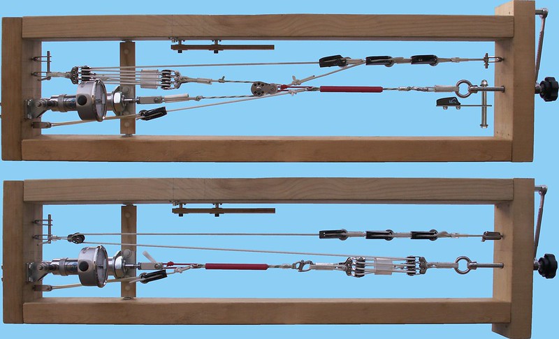
...is one of the coolest and funnest toys I ever built.
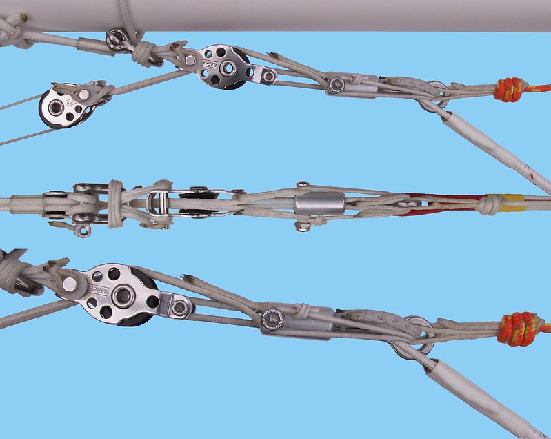
...it takes about 5kg just to compress the spring. This is added to the force needed to retract the barrel.
Two mistakes...

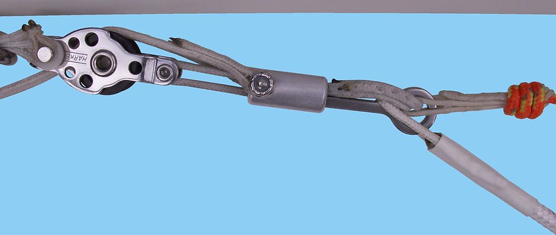
- You want the spring force ONLY enough to reliably hold the barrel forward when you're in prep and dolly loading modes. Anything more and you're working against yourself.

- Just 'cause the pin shaft is about thirty millimeters long doesn't mean you need the barrel to cover the whole length. Only the absolute tip of the shaft is doing anything and you just want the barrel far enough forward to reliably secure the tip when the release is max loaded.

http://www.flickr.com/photos/aerotowrelease/8306258400/
Image

My barrel just engages half the shaft. Joe's covers the whole damn thing. That's more wasted hand motion and the more motion you have the more of a pain in the ass the spring becomes.
- why don't you put the pulley harnessed onto the downtube inside it...
You can't.

The release harnessed to the keel moves (and you want it to).
- It pulls forward a little when the system is loaded up.
- It rotates on the keel whenever you turn or get turned away from the tug.
- You may want to adjust the trim by changing the fore/aft position.

You couldn't keep the lanyard lined up with the release unless the exit hole were huge.

You want the lanyard - inside the conduit - to exit the downtube at shallow angle (minimal bend) to the pulley and let the pulley redirect the pull as needed.
...or 3 of them in a three to one mechanical advantage ?
You don't need a three to one. You don't even need two to one. You're adding weight to the glider for the entire flight to do a job that's over in a fraction of a second.
..."WW could do that as a VG system"..
The VG system is a little easier to do. You're coming straight out of the top of the downtube to a pulley hard mounted on the keel and shooting pretty much straight forward to a rather fixed target.
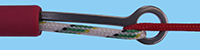
I'm surprised that the rubber band inside the controlbar...
That's a doubled quarter inch bungee. You can set the power to pretty much anything you want.

I think I set mine so it would hit the lanyard with about dozen pounds. That means the release would get hit with twice that. That would blow nearly four hundred pounds of direct load. The weak link at the top end of my bridle is 272.

(If I set the bungee tension real high the pin gets a bit hard to pull - but as it is I think it's something in the ballpark of four pounds.)
- and what about the friction of the leechline inside the plastic tubing (downtube entry and exit) ?
The nylon tubing is very slick and I'm keeping the bends very shallow. And on Zack's glider there would only be one bend at the top exit. At the bottom it would be routed through a VG pulley - just like a VG cord.
- this plastic tubing won't finally slide in or outside the hole of the downtube ?
It could. It doesn't. It's a tight fit, it's only subjected to an extremely short light lanyard pull when the when the barrel is moving back at actuation. Even if it pulled into the downtube all the way the release would still blow. (And I use a little more protrusion than what's depicted in the photos.) I check it during setup but it's pretty much a nonissue.
that's a big deal !!!
No bigger a deal than for any other release configuration at the same trim setting. It just means that for any given trim setting the point at which the top end of the bridle is fixed has to be farther aft than it would if there were no tensioner going to the nose and you don't have a lot of room to waste between the control frame apex and the front end of the release mechanism.
---
Edit - 2012/04/06 22:08:00 UTC

The first chunk of the second sentence in the above paragraph is wrong.
- The effective trim point is the intersection of the line defined by the upper length of the bridle with the keel.
- Tensioning to the nose moves the release and bridle end forward and up.
- Moving the bridle end forward and/or up results in a faster trim.
- If you tension to the nose you have to position the release farther aft to maintain the same trim.
deltaman
Posts: 177
Joined: 2011/03/29 11:07:42 UTC

Re: New Release?

Post by deltaman »

It just means that for any given trim setting the point at which the top end of the bridle is fixed has to be farther aft than it would if there were no tensioner going to the nose
yes, I misunderstood.
Steve Davy
Posts: 1338
Joined: 2011/07/18 10:37:38 UTC

Re: New Release?

Post by Steve Davy »

Tad,

The third image in the photo above shows a line exiting the pin eye with a upward bow. Why isn't it pulled straight? The middle image it looks like that line is stitched together is that true?
User avatar
Tad Eareckson
Posts: 9149
Joined: 2010/11/25 03:48:55 UTC

Re: New Release?

Post by Tad Eareckson »

OK, let's get some bearings.

- There's a loop of sixteenth inch bungee - essentially just a durable rubber band - which holds the barrel forward before the system is loaded (and is analogous to Joe's way overkill spring). It's stretched from one end of the barrel screw, through the pin eye, and back to the other end of the barrel screw.

- Lose it:


Image

so you can see what's going on a little better.

- A length of 205 Dacron leechline is routed between the pulley's becket and the pin's eye and through the barrel such that the:
-- bridle tension load is evenly distributed between four strands; and
-- strands pass through the horizontal axis of the pulley becket, over and under the barrel screw, and through the pin's eye in the vertical plane.

- I'm trying to make this construction as short as possible so's I don't limit my ability to trim the glider slow.

- The ends of the leechline are overlapped in the top loop going through the pin eye and stitched together. (There are six strands passing through the pin eye - four on the upper overlapped stitched ends loop and two on the lower vanilla one.

- The stitching of the overlapped ends is critical. I want that to be stronger than the leechline itself and I don't have much room to accomplish that goal.

- So first I just stitch the two overlapped ends together, and then...
The middle image it looks like that line is stitched together is that true?
- ...after the overlap is centered in the pin eye I stitch the quadruple overlap together aft of the eye.
The third image in the photo above shows a line exiting the pin eye with a upward bow.
- The upward bow - as you can easily see in the bungeeless photo - is caused by the element of the Shear Link being engaged by the release displacing the leechline body of the release.

- There's a stitched loop of sixteenth inch leechline engaging the 205 (5/64 inch) leechline release body's front end which allows you to tension the release to the nose.

P.S. That bridle / Shear Link design was something I tried to get away with 'cause the construction was really easy. I didn't get away with it - it's extremely wrap prone. It's majorly obsolete.
Zack C
Site Admin
Posts: 292
Joined: 2010/11/23 01:31:08 UTC

Re: New Release?

Post by Zack C »

Tad Eareckson wrote:Fifteen is ALWAYS a denominator (unless you're measuring your pull and trying to figure how much load you just dumped).
Which is what I was doing...for a pull of 11 lbs and an L/A of 15, the load is 165 lbs.
Tad Eareckson wrote:The load to actuation ratio is fifteen so 5.7 pounds is friction and 5.3 is spring. And the spring should be accounting for only 5.3 (or less) from that point on.
My math's not jiving with yours.

From what you said earlier the L/A should be constant if spring resistance is negligible. Call that ratio 'r'. So for that case,
a(l) = l/r
But with the release as it is, for loads 85 lbs or greater, the actuation force is offset by some constant:
a(l) = l/r + c
We have two data points for loads 85 or greater:
a(85) = 11
a(330.7) = 17.6
From those we can solve the equation and get:
r = 37.02
c = 8.93
a(l) = l/37.02 + 8.93
a(100) = 11.63, L/A = 8.60
a(200) = 14.33, L/A = 13.95
a(300) = 17.03, L/A = 17.61
These numbers seem reasonable, as does the ~9 lbs the spring adds (which is also consistent with your original estimate). However, this would mean the L/A with no spring resistance is ~37. That seems more than a bit much. So either 37 is indeed correct, the data point Joe gave me is inaccurate, or the premises on which the equations are based (which I got from you) are incorrect.

(If anyone is wondering the point of all this, I'm just trying to predict what kind of difference we could expect with a negligible spring resistance.)
Tad Eareckson wrote:I wish I could get you to do fewer equations and more drilling.
There's a reason I'm a programmer instead of an engineer. I don't even own a drill.

Zack
Post Reply